miercuri, 27 ianuarie 2016
Alfa 147 - Oil & Oil Filter Change
You will need:
-2 x axle stands & 2 x chock blocks
-oil filter removal tool
-new oil filter
-4.5 litres of 10w40 semi-synthetic engine oil
-bucket (preferably small enough to fit under the car while its on the stands)
-8mm allen key
-1 x 10/11/12/13mm spanner
-1 x funnel
-gloves (i use latex ones but whatever you prefer )
)
If possible try to do this around 45mins or so after
First off, jack the car up and put the axle stands under it and chock blocks behind the rear wheels to prevent rolling:
OIL FILTER CHANGE
Once done, remove the oil cap (to allow the passage of air and fluids thereby allowing the oil to drain out easier)
Your new filter should look something like this:
Put on your gloves.
Now, from standing infront of the driver's side front wheel and looking under the car, to your right slightly you should see the oil filter location (circled in red in pic below)
Below is a picture of how to affix the oil filter removal tool to the oil filter (old one on the car, i just used the new one as it's easier to show you), there should be instructions on the packaging when you buy the tool anyway.
When you have the tool attached to the old filter, use it to turn the old filter in an anticlockwise motion and as you do so, place the bucket beneath it to catch the filter and the used oil contained within.
Allow the oil to drain till it slows to a drip every minute or so, then using some new engine oil, dip your finger in and rub it around the rubber gasket at the top of the filter. Use tissue or a cloth to clean all old oil from the oil filter mount. Then screw the new filter into place.
Screw in until hard to turn.
New filter in place:
OIL CHANGE
Unfortunately my camera died at this point, but oh well
I got a snap of where the sump nut is anyway (circled in red below)
Anyway, put the 8mm Allen Key into the nut, and then put the ring end of the spanner around the Allen Key to give you extra leverage.
Then pull away at it (anticlockwise!) and it'll start to give. Grab the bucket and position it under the nut, but remember that the oil will pour out in the direction the hole is facing so make sure your bucket is in the right place
Once the oil is drained, clean the area around the sump nut hole and the nut itself, and screw the sump nut back in place.
Then put the funnel into the oil hole in your rocker cover and slowly pour in you new oil.
Job done.... almost
-2 x axle stands & 2 x chock blocks
-oil filter removal tool
-new oil filter
-4.5 litres of 10w40 semi-synthetic engine oil
-bucket (preferably small enough to fit under the car while its on the stands)
-8mm allen key
-1 x 10/11/12/13mm spanner
-1 x funnel
-gloves (i use latex ones but whatever you prefer
)If possible try to do this around 45mins or so after
First off, jack the car up and put the axle stands under it and chock blocks behind the rear wheels to prevent rolling:
OIL FILTER CHANGE
Once done, remove the oil cap (to allow the passage of air and fluids thereby allowing the oil to drain out easier)
Your new filter should look something like this:
Put on your gloves.
Now, from standing infront of the driver's side front wheel and looking under the car, to your right slightly you should see the oil filter location (circled in red in pic below)
Below is a picture of how to affix the oil filter removal tool to the oil filter (old one on the car, i just used the new one as it's easier to show you), there should be instructions on the packaging when you buy the tool anyway.
When you have the tool attached to the old filter, use it to turn the old filter in an anticlockwise motion and as you do so, place the bucket beneath it to catch the filter and the used oil contained within.
Allow the oil to drain till it slows to a drip every minute or so, then using some new engine oil, dip your finger in and rub it around the rubber gasket at the top of the filter. Use tissue or a cloth to clean all old oil from the oil filter mount. Then screw the new filter into place.
Screw in until hard to turn.
New filter in place:
OIL CHANGE
Unfortunately my camera died at this point, but oh well
I got a snap of where the sump nut is anyway
(circled in red below)Anyway, put the 8mm Allen Key into the nut, and then put the ring end of the spanner around the Allen Key to give you extra leverage.
Then pull away at it (anticlockwise!) and it'll start to give. Grab the bucket and position it under the nut, but remember that the oil will pour out in the direction the hole is facing so make sure your bucket is in the right place
Once the oil is drained, clean the area around the sump nut hole and the nut itself, and screw the sump nut back in place.
Then put the funnel into the oil hole in your rocker cover and slowly pour in you new oil.
Job done.... almost
Alfa 159 - How to change key fob/case
Tools needed:
1 small phillips screwdriver
1 small flat screwdriver
1 opening tool or larger flat screwdriver
Step 1:
Remove the emergency key (press the small button on the key an pull it out)
Step 2:
Remove the battery from the remote
Step 3:
Insert the small flat screwdriver at the bottom of the remote where the rubber buttons meet the plastic case and remove the rubber buttons.
Step 4:
Unscrew the small phillips screw.
Step 5:
On the front of the remote insert either an opening tool (used for phones and stuff) or a larger flat screwdriver and pry open (as you where to screw a screw) the two parts of the remote. ONLY pry open the remote on the top/front part of the remote (as in the picture below) you will be unable to open the key from the lower side as it has a clam shell system holding in place.
Step 6:
Once open, the remote will open in 2 like a clam shell
Step 7:
Remove the electronic plate, and your done
Step 8 (removing the key blade):
This was a little tricky, as the blade is set in place by a small bolt/pin, I did not manage to remove the bolt, tried in many ways but with no luck. So I examined the tiny bold/pin from my new remote and decided to approach the matter with force
I took a pair of pliers and tore the key from the plastic holding, the pin just popped off with absolutely no damage to the key blade.Reverse the order on your new remote
As I said, bought the remote off ebay (italy) ( http://www.ebay.co.uk/itm/1805610056...84.m1439.l2649 ) cost me 55 euro (48GBP) shipping included, way less the my dealer asked for and didn't have to leave the car in the shop for programing and stuff. Took me about 20 min to swap, will take much less now that I did it once
Here the pics for the steps above and the result:
Alfa Romeo TS, JTS, JTD & V6 - Change a thermostat on a twinspark
This is by no means the definitive guide to changing a thermostat but is how I did it (with inspiration from Andymac). Its meant as a rough guide and I take no responsibility for you damaging your own car whilst using this info.
You will need a new thermostat, thermostat gasket (mine came with the stat), 1x 29-41mm hose clip, 1x 10-13mm hose clip and 2x 13-19mm hose clips as well as an assortment of tools.
1. Open bonnet and remove air intake pipe that goes from the airbox to the throttle with 7mm hex socket.

CAUTION: do not turn the ignition on with the temp sender disconnected.
2.Remove big hose at the front of the thermostat (lots of coolant will come out), the small hose at the top, the hidden hose underneath at the front and disconnect the temp sender(the bit with the wires at the top). Note there is still one hose connected at the back. Unless you have the special pliers that takes the clips off you may have to cut them.

3.Using a 13mm socket remove the two bolts that hold the thermostat onto the side of the engine. Prise the thermostat away from the engine with you hands and disconnect the last hose on the back.

4. Take time to clean the mating surface of the engine being careful not to scratch it or get debris into the engine. Wash the drained coolant out of the engine bay as well.

5.Using an appropriate spanner, transfer the temp sender to the new thermostat giving it a good clean with solvent as well. You can buy new ones for about £15 but I am too mean.
For added support you can remove the temp sender wile the thermostat is still attached to the engine.

6.Refit in reverse order using the two 13-19mm clips on the lower hoses, one 10-13mm clip on the top hose and the big 29-41mm clip on the front hose.

7.Refill the coolant (50% mix) upto the max line and squeeze several times on some of the big hoses to bleed slightly. Then refil back to max and replace cap.
8. Re-install air intake pipework.
9. Start the engine and look closely for any leaks. Let the engine run up to normal temp while keeping an eye on the coolant level and for leaks.
10. let cool down for a couple of hours and refill the coolant to max, as the system will have bled itself.
11. The next few times you use the car check the coolant level before you start and top up if neccesary. Make sure to check the coolant level with the cap removed.
12. Enjoy
You will need a new thermostat, thermostat gasket (mine came with the stat), 1x 29-41mm hose clip, 1x 10-13mm hose clip and 2x 13-19mm hose clips as well as an assortment of tools.
1. Open bonnet and remove air intake pipe that goes from the airbox to the throttle with 7mm hex socket.
CAUTION: do not turn the ignition on with the temp sender disconnected.
2.Remove big hose at the front of the thermostat (lots of coolant will come out), the small hose at the top, the hidden hose underneath at the front and disconnect the temp sender(the bit with the wires at the top). Note there is still one hose connected at the back. Unless you have the special pliers that takes the clips off you may have to cut them.
3.Using a 13mm socket remove the two bolts that hold the thermostat onto the side of the engine. Prise the thermostat away from the engine with you hands and disconnect the last hose on the back.
4. Take time to clean the mating surface of the engine being careful not to scratch it or get debris into the engine. Wash the drained coolant out of the engine bay as well.
5.Using an appropriate spanner, transfer the temp sender to the new thermostat giving it a good clean with solvent as well. You can buy new ones for about £15 but I am too mean.
For added support you can remove the temp sender wile the thermostat is still attached to the engine.
6.Refit in reverse order using the two 13-19mm clips on the lower hoses, one 10-13mm clip on the top hose and the big 29-41mm clip on the front hose.
7.Refill the coolant (50% mix) upto the max line and squeeze several times on some of the big hoses to bleed slightly. Then refil back to max and replace cap.
8. Re-install air intake pipework.
9. Start the engine and look closely for any leaks. Let the engine run up to normal temp while keeping an eye on the coolant level and for leaks.
10. let cool down for a couple of hours and refill the coolant to max, as the system will have bled itself.
11. The next few times you use the car check the coolant level before you start and top up if neccesary. Make sure to check the coolant level with the cap removed.
12. Enjoy
Alfa GTV & 916 Spider - Full headlight lens cleaning guide
Tools needed:
Steps:
- Large bladed chisel (or large flat blade screwdriver, but undesirable)
- Star screwdriver (for removing engine bay cowling)
- Microfiber cloth
- Water (or weak cleaning solution)
- Retracting blade (for cutting caulking)
- Gloves and eye protection in case you chip the glass (or else you’ll end up like me
 )
)
Steps:
- Remove engine bay cowling by unfastening screws in 4 locations (circled)
- Remove 3 lens clips located around the lens (circled), using a large bladed chisel
- Remove and discard any dirty caulking (coloured black), using a large bladed chisel. Be cautious not to scuff the light housing (grey).
- Use large bladed chisel to prise the lens away from the housing. This needs to be done at the top of the lens (not on the clip area): insert chisel at union of lens top and housing (shown in picture); then apply slow progressive force until the glass starts to move. Don't try and force the whole glass off in one go - the caulk is similar to Blu-Tack and needs to have time to stretch.
- Cut the clean caulking (white) with retracting blade (or something similar)
- Remove entire lens, or leave bottom caulking attached and hinge down (like I have done)
- Clean the inside of the lens with a microfiber cloth and water (or weak cleaning solution). Heed caution in cleaning the reflectors (evengentle cleaning may remove some silvering)
- Replace the lens onto the housing amidst clean caulking, ensure that caulking is redistributed if required
- Attach lens clips to lens (easier if you work from back to front, from housing first then pressure onto lens clip area)
- Reattach engine bay cowling
- Compare before/after difference and increase smugness by 10 points

Alfa Romeo - How to change the cam variator on a 16V Twin Spark engine
The cam variator
How to change the cam variator on a 16V Twin Spark engine.
By Jaap Bouma.

The Achilles heel of the 16V twin spark engines has always been the phase variator on the inlet camshaft. According to an Alfa Romeo service bulletin, there have been several editions, the earlier of which were particularly prone to premature failure. A service bulletin (Pages 1 2 3, scans by Henry Yorke) indicates that the earliest version cannot be replaced without replacing the inlet camshaft. Later versions can be replaced or even repaired with a seal/spring kit. Personally I wouldn’t bother with the repair kit, because in my experience the splines in the variator are also prone to wear. On my car this gave between 1 and 2 mm of play at the circumference of the pulley.
Replacing the variator is a fairly straightforward job, provided you have the right cam locking tools to set the timing correctly. If you don’t have the cam locks, don’t even think about doing this job. Depending on the condition and mileage of the engine, you may decide to combine this job with some other jobs. The water pump is an example. It doesn’t have a reputation for failing, but on my car it had been on the engine for over 195,000 kms, and it’s not expensive, so I decided to renew it regardless of condition.
Finally, on a job like this, where you will be opening up the engine on the car, cleanliness is essential. If you get sand, dirt or grit in the engine you’re well and truly up that creek. I wouldn’t do this job outdoors, especially if it’s windy.
What you’ll need
Ricambi (replacement parts)
The following parts are essential if you’re going to do the job properly:
- Phase variator
- Timing belt
- Balance shaft belt
- Timing belt tensioner complete with idler pulley
- Balance shaft belt tensioner
Then there are parts that may not be too badly worn, but on high mileage engines I would recommend changing them anyway. These include:
- Camshaft oil seals
- Inlet camshaft bearing shells (the bearing that the variator runs in, the other cam bearings have no shells)
- Poly-V belt (PS pump, alt)
- Water pump
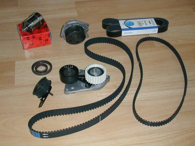
Photo 1: The new parts you’ll need. From top left: variator, water pump, poly-V belt, camshaft oil seals, balance belt tensioner, timing belt tensioner (white) with idler, timing belt and balance shaft belt. The bearing shells for the variator are not in the picture.
Tools
The workshop manual says that you will need a number of special tools. These tools are available from your dealer, but in my experience you may have to wait for anything from 6 to 18 months, and they are expensive. Fortunately, the job can be done without most of these tools. The only ones you most definitely will need are the two cam locking tools. I got my set from GGB Engineering in London
The bolts on the spark plug cover, valve cover and inlet camshaft wheel are of a Torx-like type called RIBE, but a Torx T40 bit will work equally well and is more easily available.
The more or less complete list of tools required is as follows:
- RIBE no. 7 (I think) sockets or keys OR Torx T40 (both short and long)
- Torx T30 key or socket for variator solenoid
- Allen keys 5 and 6 mm
- Sockets and spanners in sizes 10, 13, 15, 19 mm (I only use six-sided sockets).
- Torque wrench
- A homemade tool for the variator and the camshaft pulleys (see picture below)
- A steel pin, 8mm diameter, ca. 10 cm long (4”)
- A bench vise
- Thread locking compound (Loctite) medium and extra strong
- Non-hardening gasket compound, non-silicone! (I like Blue Hylomar or Comma Red)
- Lots of brake cleaner, tissue, rags, brushes etc.
Of course, the more tools you have the easier the job will be.
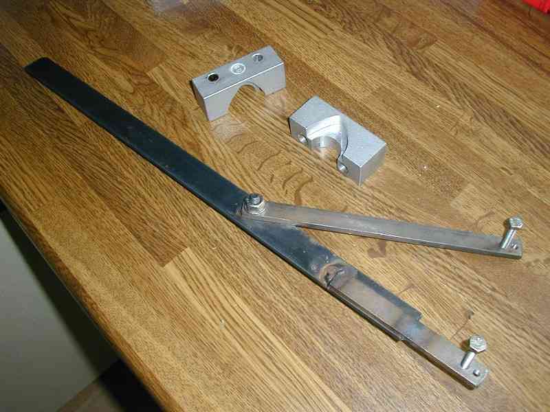
Photo 2: Camshaft pulley tool and camshaft locking caps
Dismantling
First step is to clean the engine bay. Put some layers of cardboard underneath the car to catch any oil and cleaner. Remove as much of the oily crud that has collected in all those nooks and crannies waiting to ruin your engine. Drain the coolant if you’re going to do the water pump, and remove the short hose between engine and expansion tank.
Raise the front of the car on axle stands and remove the right-hand front wheel. Remove the plastic cover plate that sits in front of the crankshaft pulley.
Find the Top Dead Center mark on the crank pulley and the corresponding mark on the lower timing belt cover. Turn the engine until the TDC marks line up (put the car in fifth and turn the brake disc to turn the engine). Remove the oil filler cap and check that the cam lobes for cylinder 1 are pointing toward the rear of the car. If they are not, turn the crankshaft another full turn until the timing marks line up and the cam lobes below the filler cap point backwards. Piston 1 is now at TDC on the compression stroke. The notches on the balance shaft wheels should line up with the marks on the engine block.
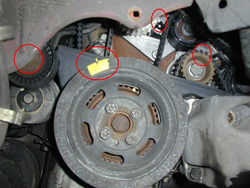
Photo 3 showing the poly-V tensioner bolt, TDC marks, tensioner indicator and balance shaft notch.
Working from the wheel arch, remove the poly-V belt. Use a 15mm spanner on the tensioner pulley bolt (see photo) to push the tensioner back (rotate counter-clockwise), until you have enough slack to slip the belt off the PS-pump pulley. A second pair of hands comes in handy here. Remove the belt and bin it.
Loosen the four allen bolts (6mm) holding the crankshaft poly-V belt pulley. Check that the TDC marks still line up. Undo the four allen bolts all the way by hand. Remove the pulley.
Remove the four allen bolts that hold the lower timing belt cover and remove the cover. IMPORTANT: Mark the crankshaft toothed pulley and the engine block with paint to make your own TDC marks.
Back at the top of the engine, remove the spark plug cover (six RIBE bolts).
Undo three allen bolts and lift up the coil pack assembly. It helps if you pull the high tension leads for the secondary spark plugs first. Put to the side as far as the cables allow.
Pull the injector plugs and the variator solenoid plug. Unclip the plastic rail holding the cables from the fuel rail and move the whole thing out of the way as far as possible.
Remove the allen bolts from the black plastic timing belt cover, and pull the cover upwards to remove.
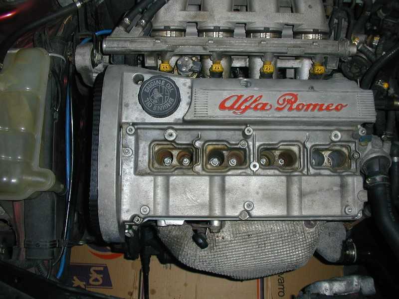
Photo 4: A clean engine.
Do some more cleaning. The valve cover should be absolutely spotless, in particular around the edges. Clean out the spark plug wells, as the valve cover tends to leak oil into them. Clean the timing side of the cylinder head and engine block as much as possible, especially behind the camshaft pulleys. It should look something like this:
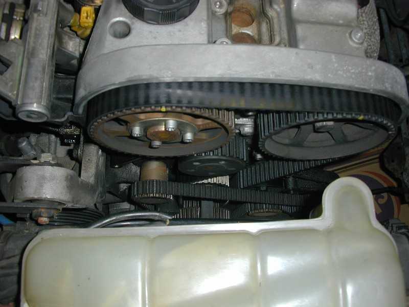
Photo 5: Belts and pulleys everywhere
Note the white timing belt tensioner wheel, which is the upgraded type. If yours is black, be very thankful that it’s still in one piece.
Remove the belts from the engine. Undo the 10mm nut at the back of the balance shaft belt tensioner (just above the oil filter), and remove the tensioner and the belt. Loosen the 13mm nut on the white timing belt tensioner wheel, and slide the timing belt off of the pulleys.
Undo three allen bolts (6mm) and remove the timing belt tensioner – idler assembly.
Optional: undo two 13mm bolts and try to remove the water pump without marking the cylinder head mating face.
You’re now ready to open up the engine. Wash your hands, put on a clean boilersuit, and brush your teeth.
Undo the nine RIBE bolts and lift off the valve cover. Be careful not to damage the rubber seal. Use some tissue to soak up the worst of the oil from the mating faces and the bearing caps. Check the camshafts for wear. The tips of the lobes will be shiny, but any wear on the up- and downslopes is bad news. Most likely to wear are the first two lobes on the inlet camshaft, as they sit right underneath the oil filler cap where sand or the oil filler nozzle at your friendly local dealer can get at them. Here’s a close-up of what I found:
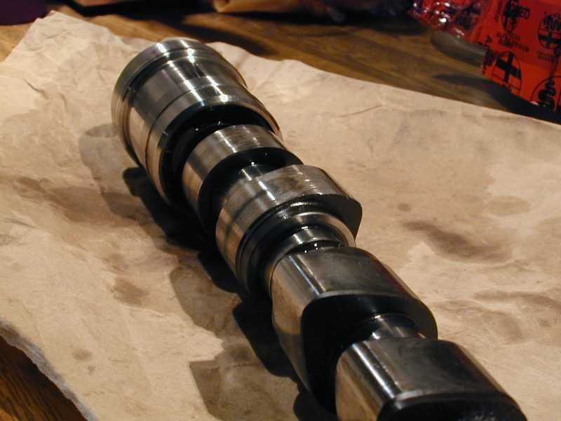
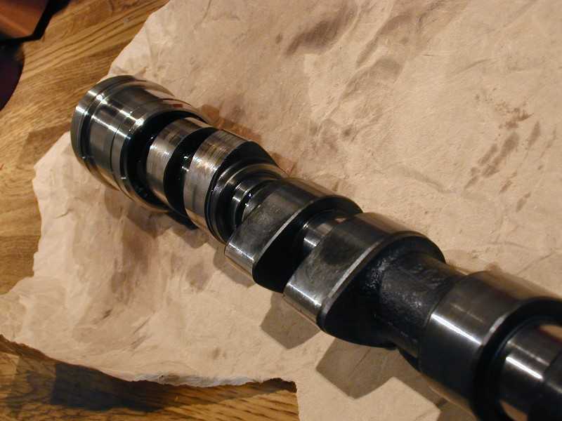
Photos 6 and 7: this camshaft is pretty much dead.
Lobe number 1 had been worn away until the valve lift was just a few millimeters (1/8 in) instead of around 10mm. Amazing that the car still ran as well as it did. Which meant another trip to the dealer for a new camshaft and 8 new cam followers (hydraulic tappets). Bugger!
Remove the camshaft pulleys. The inlet pulley is fitted with four RIBE bolts (I used a Torx T40 socket), the exhaust cam pulley with a 19mm bolt which is TIGHT (or should be). Use the pulley tool to keep the pulleys from turning.
Undo the four bolts (10mm) holding down the camshaft bearing end cap next to the pulleys and remove the end cap. On these bolts I would definitely use a six-sided socket rather than the more common 12-sided tools, because the fit on these bolt heads is quite loose. Similar for the other camshaft bearing caps. Remove the small oil seal from the exhaust camshaft end.
IMPORTANT: Mark the inlet camshaft bearing caps (1 to 5). The numbers cast into their tops are meaningless: I found numbers 1, 4, 2, 4 and 14 respectively. Gradually undo the bearing cap bolts, undoing all the bolts just half a turn, then all of them another half turn, until the valves have all closed. (If you remove the bolts and caps one by one, the force from the valve springs may lift one end of the camshaft, damaging the bearing cap on the other end.) Remove the bearing caps.
Lift out the inlet camshaft. Clamp it in a vise with soft jaws (I used bits of wood). Using the homemade tool, unscrew the phase variator from the camshaft. This may be very tight, as it’s loctited in place. You may need to use heat to break the bond, but be VERY careful with this, as you don’t want to damage the surface treatment (hardening) of the camshaft.
Reassembly
My manual doesn’t say anything about the variator and how to fit it, but here’s how I did it. Don’t blame me if it doesn’t work for you.
Clean the threads in the camshaft and on the variator. Put red Loctite (extra strong) on the threads of the new variator, taking care not to get any into the oil channel, and screw it into the camshaft. Tighten with the pulley tool (see picture) and leave overnight for the Loctite to cure fully. You can continue to fit it now, but don’t turn or start the engine until the Loctite has cured.
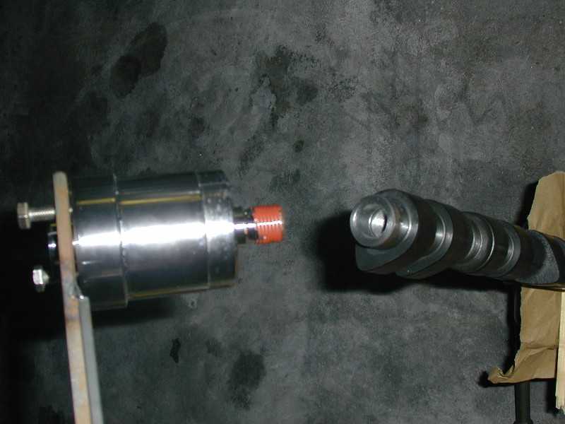
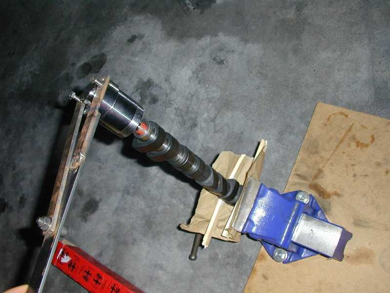
Photos 8 and 9: fitting the new variator to the camshaft. Be careful not to mark the surface of the variator where it runs in the bearing and oil seal.
Remove the old variator bearing shells from the cylinder head and the camshaft bearing end cap. Clean the bearing recesses and fit the new shells. Put some oil on them. If you’re replacing the camshaft as I was, take out the cam followers (use a magnet or your fingers) and put in eight new ones.
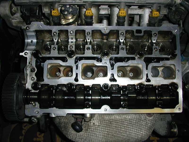
Photo 10: the head with a new bearing shell fitted (left) and the cam followers removed. Note the locating dowels for the bearing caps.
CRITICAL STEP: FOLLOW THE NEXT INSTRUCTIONS OR YOU WILL RUIN THE BEARING CAPS AND CONSEQUENTLY THE CILINDER HEAD!!!!
Put the camshaft back in with the cam lobes for cylinder 1 pointing up and towards the rear of the car. Place bearing caps 1, 3, 4 and 5 on the camshaft and GRADUALLY tighten the bolts most of the way, but not fully. Now fit bearing cap 2 (the one with the oil supply for the variator). This cap controls the end float of the camshaft, so jiggle the camshaft lengthways until the cap slots over the locating dowels. If you just fit it and tighten the bolts, chances are the cap will catch on the edge of the dowels and you’ll end up ruining the cap as you tighten the bolts. You have been warned! Once the cap is in place tighten the bolts on all caps.
Oil the new oil seals and slide them over the camshaft ends, but don’t push them fully home yet.
Very carefully clean the mating face of the camshaft bearing end cap and the head, removing all traces of the old gasket compound. Put some liquid gasket on the bottom of the end cap and fit it over the camshafts. Push the oil seals fully home.
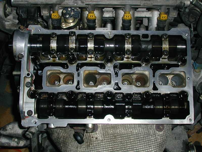
Photo 11: new camshaft, cam followers, bearing caps and camshaft bearing end cap in place.
Refit the camshaft pulleys, but don’t fully tighten the bolts.
Fit the water pump, which should come with a new O-ring. This is a bit of a pig, because the O-ring tends to slip out of its groove, which causes water leaks and misalignment of the timing belt wheel. Not good. I used a small mirror to check all the way round before pushing the pump fully home. Use a little Loctite medium on the bolts.
Fit the new timing belt tensioner – idler assembly. Use some Loctite medium on the three bolts. Don’t tighten the nut on the tensioner wheel yet.
Fit the new balance shaft belt tensioner, but do not tighten the nut yet.
Remove the inlet camshaft bearing cap on cylinder 2 (you marked this cap as number 3) and the exhaust camshaft bearing cap on cylinder 3. Fit the cam locking tools taking care not to damage them on the dowels.
Check your temporary TDC marks on the crankshaft toothed pulley.
Now fit the timing belt around the crankshaft toothed pulley, tensioner, water pump, idler, and camshaft pulleys. Fit the balance shaft belt around the crankshaft toothed pulley, tensioner and balance shaft pulleys, making sure that the marks (small notches) on the balance shaft pulleys are lined up with the marks on the block. For both belts, make sure that the arrows on the belts correspond to the direction of travel.
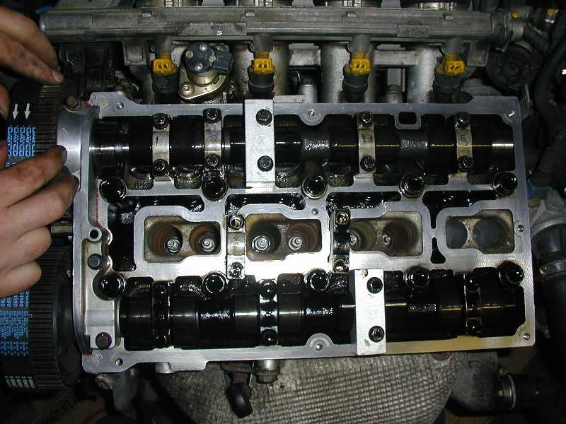
Photo 12: fitting the timing belt with the cam locks in place.
Refit the bottom timing belt cover and check that the TDC marks still line up. If they don’t, fiddle with the crankshaft and the belts and the whole lot until everything does line up.
Fit the 8mm pin (see tools list) into the hole next to the timing belt tensioner, and use that and a screwdriver or similar to set the tension of the timing belt to maximum (pointy indicator on tensioner points at the steel pin). Tighten the 13mm nut on the tensioner wheel.
Using a screwdriver or similar, adjust the balance belt tensioner until the indicator sits in the middle of the cut-out in the hexagonal bolt head in the center of the tensioner wheel (if you look at it you will understand). Tighten the 10mm nut at the back of the tensioner bracket. Also tighten the bolts on the camshaft pulleys, using the pulley tool to hold the pulleys.
Remove the cam locks and refit the bearing caps. Turn the engine by hand through two full revolutions, taking care not to let the engine turn backwards at the end of it; not even slightly!!
Adjust the timing belt tensioner, reducing the tension until the indicator points at the little hole in the base of the tensioner. Check that the balance shaft belt tension is still correct. You should end up with the timing side of the engine looking something like the picture below. Note the notches on the balance shaft pulleys.
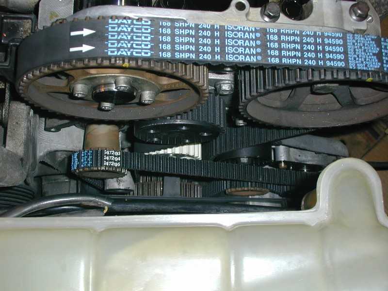
Photo 13: new belts, tensioners: looking good.
Refit the valve cover. I like to use liquid gasket on the valve cover gasket, is this is prone to leaking oil all over the place. Be careful not to overtighten the bolts, as this may crack the cover.
Refit the remaining bits and pieces, connect everything up and put in new coolant. Refit the road wheel, take the car off the axle stands. Go out on a test drive and enjoy a reborn Alfa Romeo engine. You’ll be amazed at the difference.
The variator solenoid
The phase variator is controlled by the variator solenoid sitting between the fuel injectors for cylinders 1 and 2. It’s an electromagnetic actuator that operates a hydraulic valve against a spring (see photo). On older cars, it may start to leak oil onto the inlet manifold. I took the opportunity to fix this leak at the same time that I did the variator, because the valve cover has to come off to undo one of the solenoid bolts.
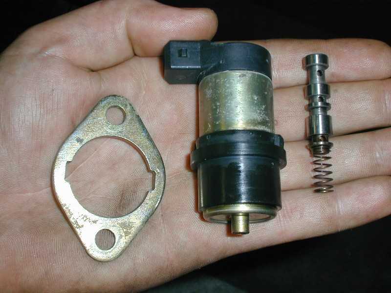
Photo 14: locking plate, solenoid and valve piston with spring.
I found that there is no seal or gasket on the solenoid. Instead, the bore that it sits in has an oil drain hole through which oil can flow back towards the sump (see green arrow).
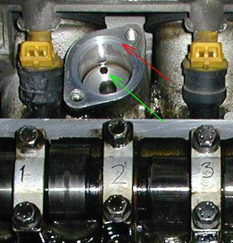
Photo 15: solenoid bore with drain hole (green arrow) and recesses edge (red arrow)
On older engines, crankcase pressure will force oil past the solenoid to the outside, causing the oil leak. I put some liquid gasket in the recessed edge (red arrow), taking care not to get any into the bottom of the bore. I then very carefully slid the solenoid back in, and refitted its locking plate and bolts with a little Loctite medium. This seems to have done the trick, but it’s early days yet. Also, it seems to me that the symptom of an oil leak because of crankcase pressure must be a sign of worn cylinder bores. So the next job looms on the horizon….
Torque settings
General note: I always use a torque wrench wherever possible. I’m sure that the mechanic at my local garage doesn’t, and maybe it’s not always necessary, but it does give me peace of mind. But it’s up to you whether you want to do so or not.
Crankshaft pulley bolts 21-26 Nm 15-19 lb.ft
Timing belt tensioner nut 24-29 Nm 18-21 lb.ft
Balance belt nut 12 Nm 9 lb.ft
Inlet camshaft pulley bolts 12 Nm 9 lb.ft
Exhaust camshaft pulley bolt 100-124 Nm 74-91 lb.ft
Camshaft bearing cap bolts 13-16 Nm 10-12 lb.ft
Valve cover and timing belt cover bolts 9 Nm 7 lb.ft
Water pump bolts 17-21 Nm 13-15 lb.ft
Variator solenoid bolts 14-20 Nm 10-15 lb.ft
Disclaimer: Ohh, you know, the usual. I wrote this down from memory. It’s only a general guideline. It may not be complete. Follow the procedure at your own peril. Buy the workshop manual. I’m not responsible. Use common sense. Don’t blame me if your engine blows up. You shouldn’t have tried it in the first place.
Abonați-vă la:
Postări (Atom)